Unlocking Electronics: Understanding Electronic Component Symbols

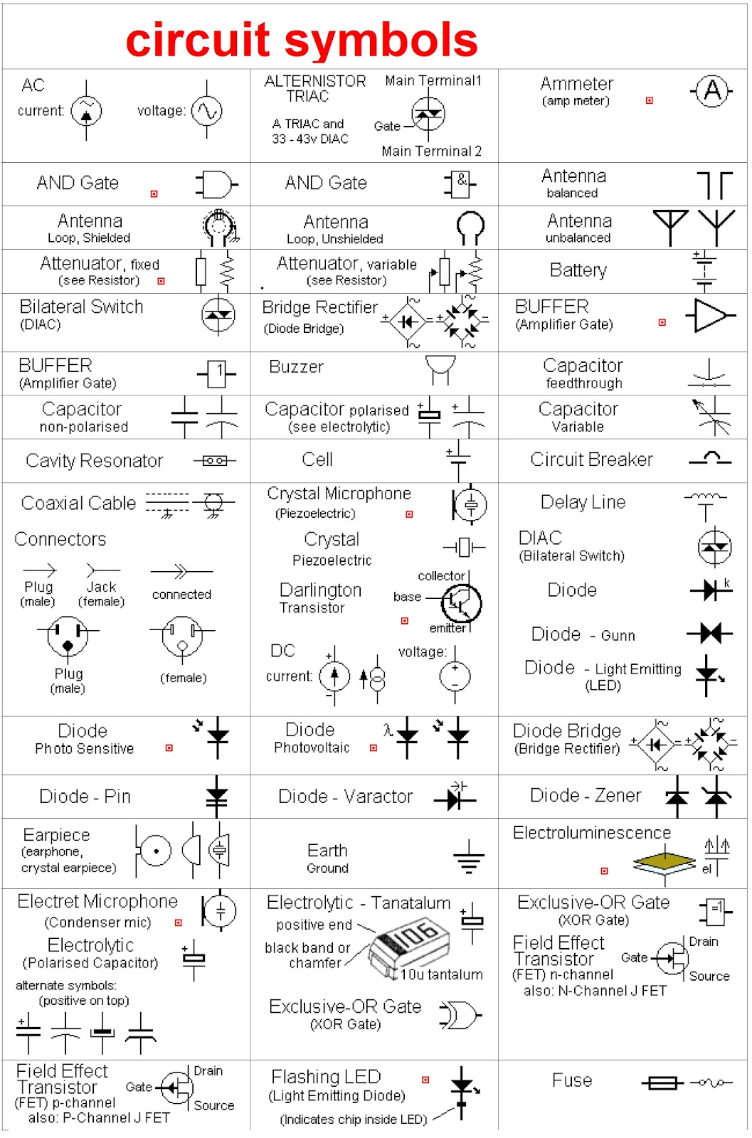
Imagine trying to assemble a complex piece of furniture without instructions. Frustrating, right? Similarly, in the world of electronics, deciphering a circuit diagram without understanding the graphic representations of each component is virtually impossible. These graphic representations, known as electronic component symbols, are the essential language of circuit design, providing a visual shorthand for each component's function and characteristics.
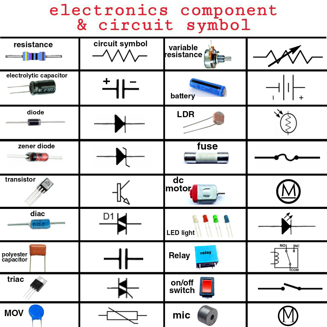
Electronic component symbols form the backbone of any circuit diagram, enabling engineers and hobbyists alike to design, analyze, and troubleshoot electronic circuits. They are a standardized set of graphical elements, each uniquely representing a specific electronic component, such as resistors, capacitors, transistors, diodes, and integrated circuits. Without a solid grasp of these symbols, navigating the intricate world of electronics becomes a daunting task.
The history of electronic component symbols is intertwined with the development of electronics itself. As the field progressed from basic circuits to complex integrated systems, the need for a standardized visual language became increasingly apparent. Early diagrams often employed ad-hoc symbols, leading to confusion and misinterpretations. Over time, standardization efforts led to the development of widely recognized symbol sets, ensuring clarity and consistency in circuit diagrams across the globe.
The importance of standardized component symbols in electronic schematics cannot be overstated. These symbols provide a universal language, facilitating communication and collaboration among engineers worldwide. Imagine a team of engineers from different countries working on the same project – a common understanding of symbols ensures everyone is on the same page, regardless of language barriers. This universal language streamlines design, troubleshooting, and maintenance processes.
One of the main issues related to electronic component symbols is keeping up with the ever-evolving landscape of electronic components. As new components are developed, new symbols need to be created and standardized. Another challenge is ensuring consistent usage of symbols across different software platforms and design tools. Despite these challenges, the benefits of standardized symbols far outweigh the difficulties, allowing for clear and efficient communication in the world of electronics.
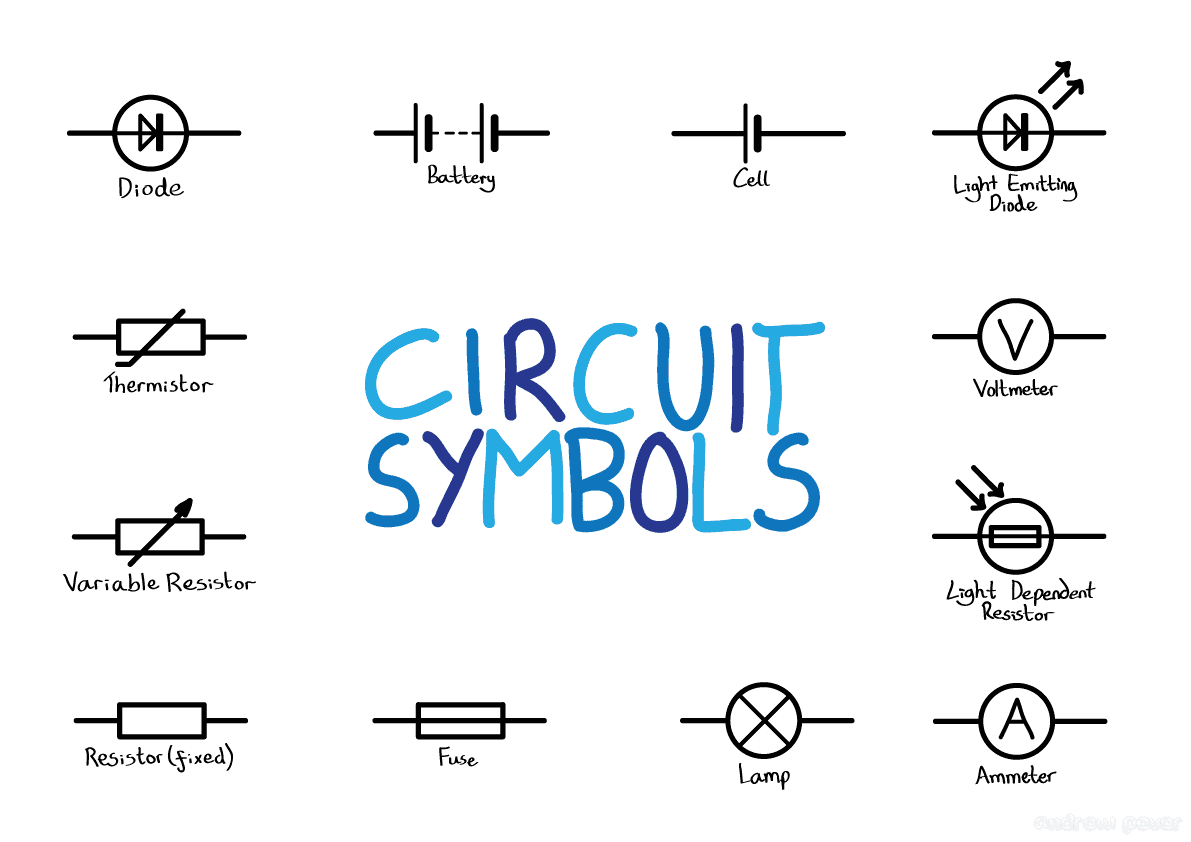
A resistor, for instance, is represented by a zig-zag line, symbolizing its resistance to current flow. A capacitor, which stores electrical energy, is depicted by two parallel lines, signifying its two plates. Even complex components like microcontrollers have their own distinct symbols, encapsulating their multifaceted functionality in a concise graphical form. Understanding these symbol representations unlocks the secrets hidden within a circuit diagram.
Benefits of using standardized electronic component symbols are manifold. First, they foster clear communication and collaboration amongst engineers and technicians. Second, they greatly simplify the process of circuit design and analysis. And third, they play a crucial role in troubleshooting and repairing electronic systems.
Creating a simple circuit involving an LED, resistor, and battery requires a clear understanding of the symbols for each component. You'd place the LED symbol, the resistor symbol, and the battery symbol, connected by lines representing wires, in a specific configuration to create a functioning circuit.
Best Practices for using electronic component symbols include: 1. Adhering to established standards like IEC or ANSI. 2. Maintaining consistency in symbol orientation. 3. Using clear and legible diagrams. 4. Providing a legend or key for non-standard or specialized symbols. 5. Regularly updating your knowledge of symbols for new components.
Advantages and Disadvantages of Standardized Electronic Component Symbols
| Advantages | Disadvantages |
|---|---|
| Universal understanding | Requires learning and memorization |
| Simplified circuit design | Can be complex for highly integrated circuits |
| Efficient troubleshooting | Constant evolution requires updates |
Frequently Asked Questions:
1. Q: Where can I find a comprehensive list of electronic component symbols? A: Resources like the IEC and ANSI standards provide extensive lists.
2. Q: How often are new symbols added? A: New symbols are introduced as new components are developed.
3. Q: Are there software tools to help learn component symbols? A: Yes, numerous online resources and software packages offer symbol libraries and tutorials.
4. Q: Why is standardization of symbols important? A: Standardization ensures clear communication and prevents errors in circuit design and analysis.
5. Q: What are some common mistakes when using symbols? A: Common mistakes include incorrect orientation, inconsistent usage, and failure to label non-standard symbols.
6. Q: What is the difference between IEC and ANSI standards for symbols? A: While largely similar, there can be minor variations between IEC and ANSI symbols for certain components.
7. Q: How can I improve my understanding of electronic component symbols? A: Practicing circuit diagram reading and design is key to improving symbol recognition and understanding.
8. Q: Are there any free resources for learning electronic symbols? A: Many websites and online tutorials offer free resources for learning electronic component symbols.
Tips and tricks for mastering component symbols include using flashcards, practicing drawing circuits, and referring to comprehensive symbol libraries. Using online simulators can also greatly enhance understanding by visualizing how components function within a circuit.
In conclusion, understanding electronic component symbols is fundamental to anyone working with electronic circuits. From designing complex systems to troubleshooting simple circuits, these graphical representations provide a universal language that transcends geographical and linguistic barriers. Mastering these symbols empowers individuals to navigate the intricate world of electronics with confidence and precision. By embracing the standardized language of component symbols, you unlock the potential to design, analyze, and innovate in the exciting field of electronics. Take the time to familiarize yourself with these essential symbols and unlock a world of possibilities within electronic circuit design and analysis. Continuing to learn and adapt to new symbols is crucial as the field of electronics constantly evolves. Don't get left behind – embrace the power of electronic component symbols and unlock your full potential in the exciting world of electronics! This knowledge will not only enhance your understanding of circuit diagrams but also empower you to design and analyze circuits effectively. Start exploring the world of electronic components and their symbols today.
Unity transform position woes troubleshooting your movement
Destins gaming scene beyond the arcade
Madison county busted newspaper unveiling public records


.jpg)

