Triangular Wave Generator Circuits: A Sonic Playground

Ever wonder how synthesizers create those crisp, futuristic sounds? Or how certain test equipment generates precise signals? The answer often lies within the intriguing realm of the triangular wave generator circuit. These clever electronic contraptions are the backbone of various applications, from audio engineering to function generators. Let's embark on a journey to discover the magic behind these waveform wizards.
A triangular wave generator, in its simplest form, is a circuit designed to produce a signal that resembles a series of ramps, rising and falling linearly with time. Unlike the smooth curves of a sine wave or the abrupt transitions of a square wave, the triangular wave offers a distinct linear character, making it a valuable tool in diverse fields. Imagine a sawtooth, but smoother, more refined – that's the essence of a triangular wave.
The genesis of triangular wave generation can be traced back to the early days of electronics, evolving alongside the development of vacuum tubes and later, transistors. These circuits initially played a crucial role in testing and calibrating electronic equipment, providing a stable and predictable signal source. As technology progressed, the triangular wave found its niche in music synthesizers, lending its unique sonic signature to countless iconic sounds.
The importance of triangular wave generator circuits stems from their ability to produce a signal with a rich harmonic content. This characteristic makes them ideal for musical applications, where they contribute to the timbre and texture of synthesized sounds. Furthermore, their precise linear nature makes them invaluable in testing and measurement applications, allowing engineers to analyze circuit behavior with accuracy.
However, designing and implementing a triangle wave generator isn't without its challenges. Achieving perfect linearity, minimizing noise, and maintaining stability across different frequencies are crucial considerations. Issues like temperature drift and component tolerances can impact the quality of the generated waveform, requiring careful design and component selection.
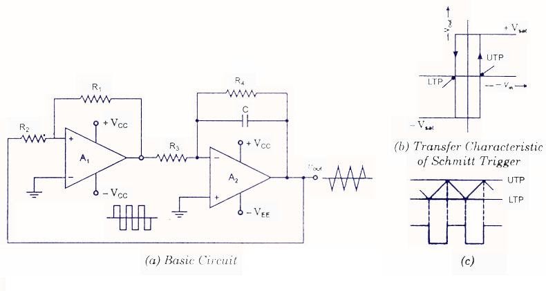
A basic triangular wave generator circuit can be constructed using operational amplifiers (op-amps) and a few passive components like resistors and capacitors. The op-amps act as integrators and comparators, shaping the wave into its characteristic triangular form. By adjusting component values, the frequency and amplitude of the wave can be controlled.
One benefit of using a triangular wave generator is its application in music synthesis. The rich harmonic content of the triangular wave allows for the creation of distinctive sounds, particularly in synthesizers and electronic musical instruments.
Another benefit lies in its use in testing and measurement. Its linear nature makes it ideal for testing the linearity of amplifiers and other electronic circuits.
Triangular waves are also useful in voltage-controlled oscillators (VCOs) for generating precise and stable frequency variations.
Designing a triangular wave generator circuit involves selecting appropriate op-amps, resistors, and capacitors based on desired frequency and amplitude. A common approach is to use an integrator followed by a comparator circuit.
Advantages and Disadvantages of Triangular Wave Generator Circuits
| Advantages | Disadvantages |
|---|---|
| Rich harmonic content for sound synthesis | Can be susceptible to noise and distortion |
| Linearity useful for testing and measurement | Requires careful component selection for optimal performance |
| Applicable in voltage-controlled oscillators | Temperature drift can affect stability |
Best Practices: 1. Use high-quality op-amps for low noise. 2. Choose precise resistors and capacitors. 3. Implement proper grounding techniques. 4. Shield the circuit from external interference. 5. Use a regulated power supply.
Real-world examples: 1. Music synthesizers. 2. Function generators. 3. Voltage-controlled oscillators. 4. Calibration equipment. 5. Analog-to-digital converters testing.
Challenges and Solutions: 1. Noise - use shielding. 2. Distortion - use high-quality components. 3. Instability - use a stable power supply. 4. Temperature drift - use temperature-compensated components. 5. Frequency limitations - optimize circuit design.
FAQ: 1. What is a triangular wave? 2. How does a triangular wave generator work? 3. What are the applications of triangular waves? 4. How do I build a simple triangular wave generator? 5. How do I troubleshoot a triangular wave generator? 6. What are the key components of a triangular wave generator circuit? 7. What are the different types of triangular wave generator circuits? 8. How do I control the frequency of a triangular wave generator?
Tips and tricks: Experiment with different op-amps and capacitor values to fine-tune the waveform. Consider using a breadboard for prototyping before building a permanent circuit.
In conclusion, the triangular wave generator circuit, with its unique characteristics, plays a vital role in a myriad of applications. From the sonic landscapes of music synthesis to the precision demands of testing and measurement, these versatile circuits continue to shape the world of electronics. Understanding the principles behind these waveform wizards empowers us to explore the fascinating intersection of sound, electricity, and innovation. Whether you're a budding electronic musician, an experienced engineer, or simply curious about the inner workings of electronic devices, delving into the world of triangular wave generation offers a rewarding and insightful experience. By understanding its history, benefits, and practical applications, you unlock a world of sonic and electronic possibilities. So, grab your soldering iron, explore circuit diagrams, and embark on your own journey into the fascinating world of triangular waves.
Unlocking effortless elegance with white chalk paint
Unlock serenity with silvery blue benjamin moore 1647 paint guide
Navigating the modern workplace with dayforce hcm


