Decoding the DPDT Switch: A Circuit Essential

Ever wondered how some circuits manage to seamlessly switch between two different sources or control two separate loads simultaneously? The answer often lies in a tiny but mighty component: the double-pole, double-throw (DPDT) switch. Understanding its schematic symbol is key to navigating circuit diagrams and harnessing its versatile capabilities. Let's delve into this essential electrical element.
The DPDT switch, in its simplest form, acts like a double-decker version of a regular on/off switch. Imagine two light switches stacked on top of each other, each controlling a separate light. That’s the essence of a DPDT switch, except it offers more complex routing options beyond simple on/off control. Its schematic symbol visually represents these connections, allowing us to understand how the switch functions within a circuit.
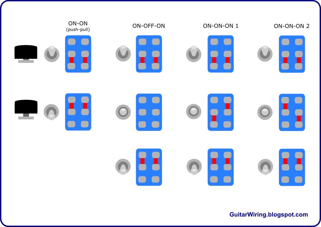
The DPDT switch schematic symbol typically consists of two sets of three contacts. Each set represents a "pole," and each pole has a common contact in the center and two throw contacts on either side. When the switch is activated, the common contact connects to one of the throw contacts, determining the path of the electrical current. This dual-pole design allows for independent control of two separate circuits or loads simultaneously.
The importance of understanding the DPDT switch symbol goes beyond simply reading circuit diagrams. It allows you to visualize the flow of electricity, troubleshoot potential issues, and design your own circuits with confidence. Whether you’re a seasoned electrician or a curious hobbyist, grasping this fundamental symbol opens up a world of possibilities in circuit design and control.
Understanding the function of a DPDT switch starts with the name itself. "Double-pole" signifies the switch controls two separate circuits, while "double-throw" indicates each pole can connect to one of two different output connections. This gives the switch its remarkable versatility, enabling it to switch between two different power sources, reverse the polarity of a motor, or control two separate loads independently.
The precise history of the DPDT switch is difficult to pinpoint, as its development likely evolved alongside other electrical switching mechanisms. However, its importance grew alongside the increasing complexity of electrical systems. As the need for more intricate control schemes arose, the DPDT switch provided an elegant and efficient solution.
One common issue with DPDT switches is contact bounce. This occurs when the contacts make and break rapidly upon switching, leading to unstable signals. Debouncing techniques, such as using capacitors or software filters, can mitigate this issue.
A simple example of a DPDT switch application is reversing the polarity of a DC motor. By connecting the motor leads to the throw contacts and switching between them, you can change the direction of the motor’s rotation. Another example is selecting between two different audio sources, routing the output of each source to a different set of throw contacts.
Benefits:
1. Versatility: DPDT switches can control two separate circuits simultaneously, making them suitable for a wide range of applications.
2. Simplified Wiring: Using a single DPDT switch can often simplify complex wiring arrangements that would otherwise require multiple switches.
3. Compact Design: DPDT switches offer significant functionality in a compact package, saving space in circuit designs.
Best Practices:
1. Current Rating: Choose a DPDT switch with a current rating appropriate for the intended load.
2. Voltage Rating: Ensure the switch's voltage rating matches the circuit voltage.
3. Contact Material: Consider the contact material (e.g., silver, gold) for optimal conductivity and durability.
4. Mounting: Use appropriate mounting hardware to secure the switch firmly.
5. Wiring Diagram: Always consult a wiring diagram to ensure proper connections.
Frequently Asked Questions
1. What does DPDT stand for? Double-pole, double-throw.
2. How many contacts does a DPDT switch have? Six.
3. Can a DPDT switch be used to reverse polarity? Yes.
4. What is contact bounce? Rapid making and breaking of contact upon switching.
5. How can I prevent contact bounce? Use debouncing techniques.
6. What are some common applications of DPDT switches? Motor reversing, source selection, backup power switching.
7. How do I choose the right DPDT switch? Consider current rating, voltage rating, and contact material.
8. Where can I find DPDT switch wiring diagrams? Online resources, datasheets, textbooks.
Tips and Tricks: Always double-check your wiring before energizing the circuit. Use a multimeter to verify connections. Consider using a breadboard for prototyping DPDT switch circuits.
In conclusion, the DPDT switch is a versatile and essential component in many electrical systems. Understanding its schematic symbol is fundamental to comprehending circuit diagrams and designing effective control schemes. By mastering its functionality and applications, you gain a powerful tool for controlling electrical circuits, from simple motor reversals to complex switching networks. Whether you’re a hobbyist or a professional, embracing the power of the DPDT switch expands your capabilities and unlocks new possibilities in circuit design and control. Take the time to explore resources, experiment with different applications, and solidify your understanding of this remarkable little switch – you’ll be surprised at the doors it opens in your electrical endeavors. The DPDT switch is a small component with a big impact, ready to empower your next electrical project.
Grey wood the undisputed king of interior design
Kashmir dispute un involvement a path to peace
Nfl week 10 predictions and spread analysis from cbs


