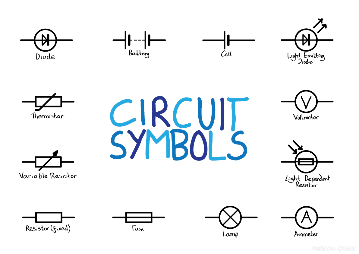
Deciphering Circuit Diagrams Electronic Component Symbols

Ever looked at a circuit diagram and felt like you were staring at an alien language? Those squiggles and lines are electronic component symbols, and understanding them is the key to unlocking the world of electronics. Don't worry, it's not as daunting as it seems. This guide will demystify these symbols and equip you with the knowledge to navigate circuit diagrams with confidence.
Electronic symbols represent the various components that make up a circuit. Think of them as shorthand for resistors, capacitors, transistors, and more. Without a standardized set of symbols, circuit diagrams would be chaotic and impossible to understand. Imagine trying to build a complex electronic device without a clear blueprint – that's the role these symbols play.
The history of electronic component symbols traces back to the early days of electrical engineering. As circuits became more complex, the need for a universal language to represent components became evident. Over time, standardized symbols emerged, evolving and adapting to the ever-growing range of electronic components. These standardized representations facilitate communication among engineers, regardless of their language or background.
The significance of a comprehensive electronic component symbol library cannot be overstated. It ensures consistency and clarity in circuit design, promoting collaboration and reducing the risk of errors. Misinterpreting a single symbol can have significant consequences, potentially leading to malfunctioning circuits or even safety hazards. A clear understanding of these symbols is essential for anyone working with electronics, from hobbyists to professional engineers.
One of the primary challenges associated with electronic symbols is keeping up with the constantly evolving technology. New components are continuously being developed, and with them come new symbols. Fortunately, organizations like the IEEE (Institute of Electrical and Electronics Engineers) maintain standards and provide resources to keep engineers and enthusiasts up-to-date. Understanding these standards ensures accurate interpretation of electronic diagrams, promoting effective design and troubleshooting.
A resistor, for instance, is represented by a zigzag line, while a capacitor is typically depicted by two parallel lines. A diode, which allows current to flow in only one direction, is symbolized by a triangle with a line across one end. Understanding these fundamental representations is the first step to understanding the functionality of a circuit.
One of the primary benefits of using standardized electronic component symbols is that it simplifies circuit analysis. By looking at a diagram, engineers can quickly identify the components used and understand their interconnections. This facilitates troubleshooting and circuit modification. Furthermore, using standard symbols streamlines the design process, allowing engineers to focus on the functionality of the circuit rather than deciphering ambiguous representations.
Another benefit is enhanced communication among engineers. Using a common language of symbols ensures everyone is on the same page, regardless of their location or background. This is particularly important in collaborative projects, where clear and concise communication is crucial.
Advantages and Disadvantages of Standardized Electronic Symbols
| Advantages | Disadvantages |
|---|---|
| Clear Communication | Keeping up with new symbols |
| Simplified Circuit Analysis | Potential for misinterpretation if not learned properly |
| Efficient Design Process |
Best Practice: Always double-check the symbol library you are using to ensure it aligns with industry standards. This helps avoid confusion and potential errors in circuit design.
Real Example: In the design of a simple LED circuit, the correct symbol for the LED and its polarity are essential to ensure it lights up correctly. Using the wrong symbol could lead to the LED not functioning as intended.
Challenge: Keeping up with the constant influx of new electronic components and their associated symbols can be challenging. Solution: Regularly consult reputable resources like IEEE standards and online component databases to stay informed.
FAQ: What does the symbol for a transistor look like? Answer: It varies depending on the type of transistor (NPN, PNP, MOSFET), but generally includes three terminals and an arrow indicating current flow.
Tip: When learning electronic symbols, start with the basic components and gradually progress to more complex ones. Practice drawing and identifying symbols regularly to solidify your understanding.
In conclusion, mastering electronic component symbols is essential for anyone venturing into the world of electronics. These symbols provide a common language for describing and understanding circuits, enabling engineers and hobbyists alike to design, analyze, and troubleshoot electronic systems effectively. While the sheer number of symbols may seem daunting at first, a systematic approach to learning, combined with consistent practice and access to reliable resources, will empower you to confidently decipher circuit diagrams and unlock the full potential of electronics. Start with the fundamentals, explore different symbol libraries, and don't hesitate to seek guidance from experienced engineers or online communities. The journey to mastering these symbols is an investment that will pay off significantly as you delve deeper into the fascinating world of electronics.
Fifa 23 on game loop unveiled
The essence of fleur de sel a journey from sea to table
Divine path system novel online reading experience


.jpg)


